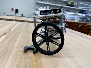
Self-Balancing Robot
Designing and building a compact, self-balancing robot by using simulation results to determine the feasibility and inform the overall design.
The main challenge with this design is that is it working against physics. For any balancing system, you want the center of mass to be directly above the rotation point and as far away as possible. Increasing the distance between these two points causes the object to fall slower giving the system more time to react before it is unrecoverable. If you've ever tried to balance a pole on your hand, you have experienced that it is easier to balance a meter sick than a pencil. However, by constraining our robot design to be compact creates a difficult design challenge that works against this principle.
A deeper dive in the details of the project and all source code is hosted on Github.
Build Process Photos

Lessons Learned
The actual V1 build came out much heavier than anticipated, this can be attributed to not accounting for the components not in CAD (wires, nuts, screws, etc.) and the 9V battery. This was added late due to the 6V AA pack not being able to reliably power both the Arduino and the motors.
The torques and speeds required for this design, are pushing these motors to their design limits. Therefore, any drop below their rated operating voltage of 6V really hurts their ability to output the required control.
The IMU used has onboard processing that provides easy access to an absolute position. Since the system is oscillating very quickly the 100Hz data stream may not be quick enough to allow the motors enough time to react.
The IMU fell out of calibration after a few tests and caused the robot to try and balance to a non-vertical position.
There is some play in the wheel shaft to the gear box that allows the body to rotate a couple degrees without the motors spinning. Since the window of stable positions is only +/- 6 degrees or so, this amount of play is not negligible.
Future Development
-
Switch to aluminum standoffs to save weight.
-
Switch to an Arduino Nano and remove the middle plate to save weight.
-
Switch to 2S Lipo battery to power motors and controller to save weight.
-
Integrate a 6V DC-DC regulator to reliably power the motors.
-
Incorporate encoder-based position control to help counteract the IMU calibration drift.
-
Simulate V2 design and reevaluate motor selection based on required torques and wheel speeds.
-
Slight increase of the body height to make the balancing easier and allow the control system more time to react.


